
An electric car is a battery with a vehicle built around it, and the battery is heavy. Every kilogram the structure gives back is range, or payload, or a smaller and cheaper pack. So when a new EV platform came to be engineered, its front subframe was designed to do something a structural automotive assembly had not done before.
It was not welded. It was glued.
The frame is aluminium throughout: four cast nodes, one large rear casting, connecting extrusions, and a bottom plate. What holds it together is adhesive and rivets. Nothing else.
Adhesive bonding in a car is not new. It is used widely on class A panels, the visible cosmetic parts where the bond carries appearance rather than load. What was new here was the structure. This frame is a load path. It is part of what keeps the occupants of the car alive in a crash, and it is held together with glue.
To Ethos Automation's knowledge at the time, no structurally integral adhesive-bonded aluminium automotive assembly had been attempted before. The line to build it did not exist either.
How the Line Runs
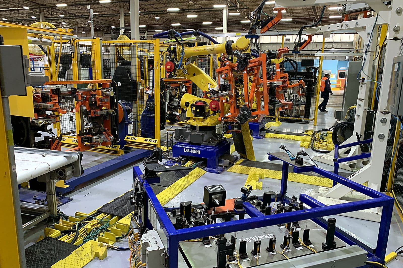
It is worth picturing the cell, because it is not what the phrase "automated assembly line" usually conjures.
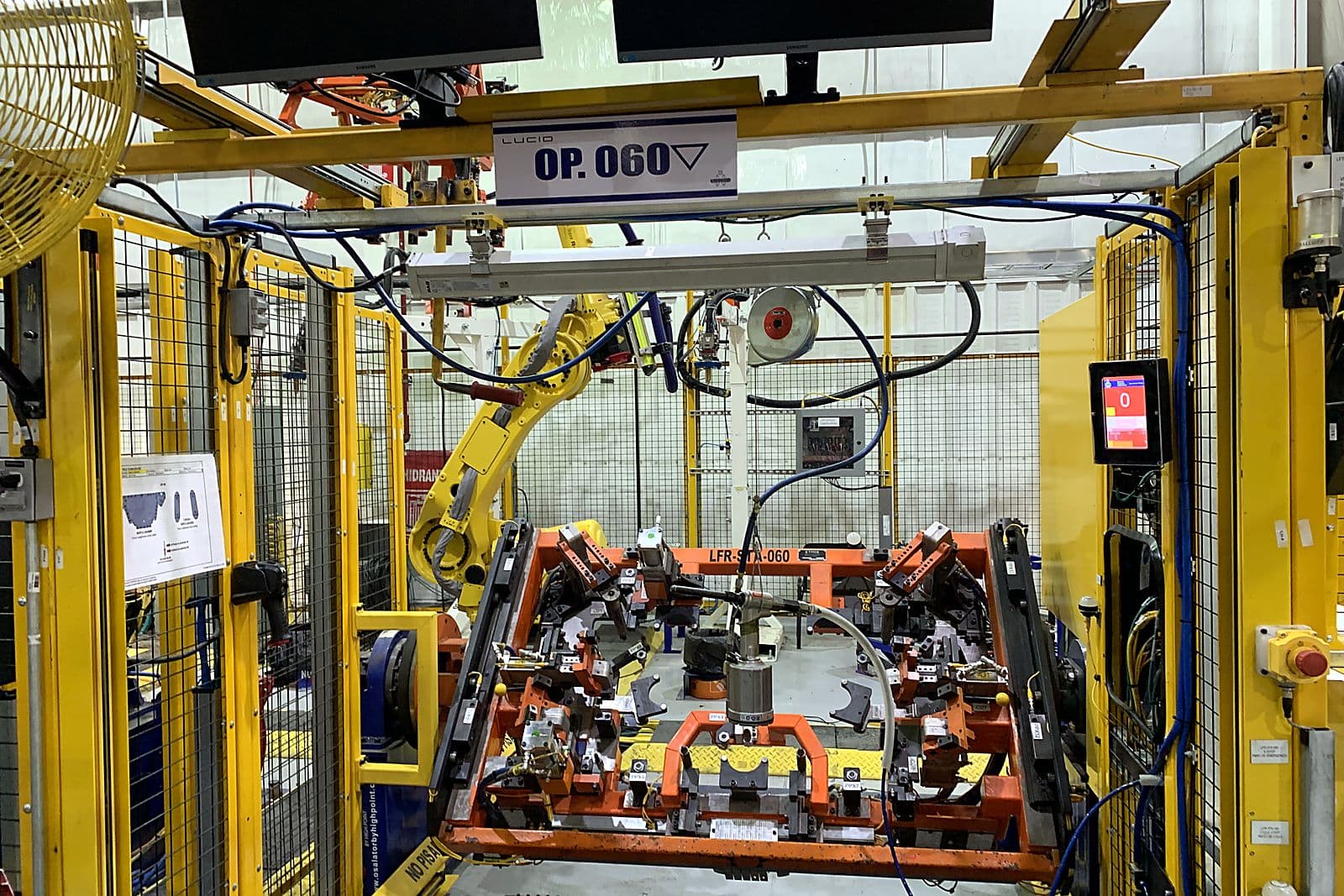
Seven stations. People load, people rivet, and robots move material. Operators place castings and extrusions into rough nets by hand. Two material handling robots pick the subassemblies and carry them between stations. And the adhesive stations do not move at all: the guns are fixed, and the robot brings the part to the nozzle, presenting each bonding surface in turn. There are two of them, one partway through the build and one near the end.
The build works up through subassemblies. The fore and aft assemblies are loaded and bonded first, then the material handler carries them to adhesive, then on to a station built around a trunnion with a side A and a side B. An operator loads extrusions into side A, walks out, palms off, and the station rotates so the far side can be loaded while the robot drops castings into the side just vacated. Then the operator walks back in and sets rivets by hand, four on one side, twenty one on the other.
From there the part goes to a check station, where the robot repositions it six times in front of the sensors so every rivet and rivnut can be confirmed present. Then to the second adhesive station. Then to the final station, where an operator sets another ten rivets, closes two more components with a pack clamp, and the finished frame comes off with an overhead crane on a lift assist.
So the honest description is a hybrid. The robots do the carrying, the presenting and the checking. The people do the loading and the riveting. What is automated is the part of the job where consistency decides whether the bond passes, and what is left to people is the part where judgment and dexterity still beat a machine.
Ninety Percent, and Nothing Showing
The specification looked simple written down. Every bond had to reach 90 percent adhesive surface coverage. No seepage, no stickout beyond three millimetres. And it would be verified by destructive testing, which means cutting finished assemblies open and looking.
And there is a great deal of it. A single frame carries roughly thirty-four metres of adhesive bead. Ninety percent coverage is not a requirement on one joint, it is a requirement on all thirty-four metres, on every frame, and the only way anyone finds out whether it was met is by destroying the part.
Simple to state, and a long way from simple to achieve, because coverage is the output of a large number of variables that all interact. Adhesive viscosity. Bead volume and bead width. Application speed. The angle between the gun and the surface. The gap between the two parts being joined. The pressure used to press them together, and for how long.
None of those numbers were available. The dispensing guns were supplied by the customer, and the gun manufacturer offered no guidance on application parameters for this use. Every one of them had to be found experimentally.
Then the geometry took away the easy answers, and it did so because of that fixed-gun arrangement.
A robot holding a gun can choose its approach. A robot holding a part cannot, or not freely: how it must grip the casting to keep the datums intact dictates how that casting can be offered to the nozzle.
The gun manufacturer specified a dispensing angle of zero to ten degrees off the surface. Part handling and cycle time forced many bonds to be laid at thirty five to fifty degrees on tapered surfaces, well outside what the equipment was specified to do. Glue applied at that angle does not spread evenly when the parts are pressed together; it smears asymmetrically, and the paths had to be rewritten to account for it.
Finding the Numbers
The adhesive work was done with FANUC R-2000iC/210F robots, 210 kilogram payload machines carrying aluminium castings to the customer's fixed guns, and it was done the only way it could be: by trying things and cutting the results open.
Because the gun is fixed and the part comes to it, the nozzle has to reach into whatever the part presents: crevices, interior features, surfaces that sit deep inside the casting. Ethos designed its own applicator nozzles for the guns to get that reach. Nozzle length then interacts with temperature, because a longer nozzle loses more heat, and temperature sets viscosity, and viscosity sets everything downstream. So the work became controlling heat relative to nozzle length to hold the adhesive at the right temperature at the point it leaves the nozzle, not where it is stored.
From there, bead width and wet-out were mapped against robot speed, which here means how fast the part travels past the nozzle. Move it slower and the bead lays down wider, which gets more coverage and also increases the chance of squeeze-out past the three millimetre limit. That speed is also cycle time, so every gain in coverage is paid for somewhere else.
The trials were logged station by station. Two rounds on each of two stations in December 2020 alone, each one a set of parts glued, assembled, cut apart and photographed.
Out of it came a set of strategies rather than a single recipe, which is the honest outcome of that kind of work. Large surfaces can take a much bigger bead. Small surfaces need only a short purge of adhesive and very little robot travel. And for the tapered surfaces that caused the most trouble, path spacing and direction turned out to be the controlling variables, with the answer being to start at the top and weave downward.
Holding a Frame That Will Not Hold Still
The second problem is the one that does not exist when you weld things.
A welded joint is fixed the instant it is made. An adhesive joint is liquid, and stays liquid while it cures, and during that time the assembly has to be held in exactly the right relationship by something other than the joint itself. Every standard clamping and nesting approach assumes you can simply squeeze the parts together. Here the clamping pressure was itself a process variable, because it sets how the adhesive spreads and how much of the surface it covers.
It also had to accommodate a gap. Two bonded surfaces need space between them for the adhesive to occupy, which is the opposite of how a fixture normally works, and nobody could say at the outset how large that gap needed to be or how precisely it could be held.
And the thing being held was flexible. Aluminium castings and extrusions, with clearances between them for glue, produce an assembly with give in it. Left to itself it would skew and distort under its own weight and under the forces applied to it.
The fixturing that came out of this was largely invented for the job.
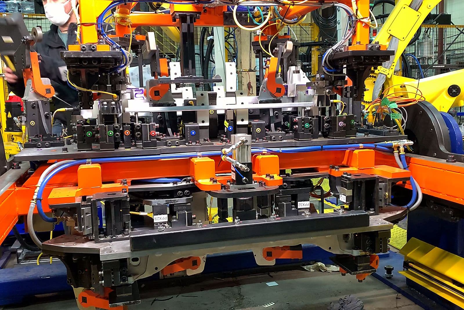
In the station that bonds the front of the frame, the standard approach would be to load one component at a time so each can be aligned to pins as it goes in. That could not be done here, because loading sequentially would destroy the datums on the castings that the bonding surfaces depend on. So operators load the extrusions into a fixture, and the material handling robot loads the castings, and both come into position simultaneously. Holding that required pressing down on the castings from above while pushing the extrusions up into them, without binding, which led to guided spring-loaded nets with experimentally determined spring pressures and heights.
To apply the mating force through the robot, Ethos developed straight hex fingers that could load the joint in one direction without dragging it sideways. Grippers were modified to run in reverse, gripping open rather than closed, to hold a part in a space too tight for a conventional gripper.
Rivet holes had to line up within two tenths of a millimetre between casting and extrusion. That drove a staged locating pin design holding concentricity to thirty thousandths along its length, which turned out to be genuinely difficult to manufacture: the trials were as much about machining and heat treatment as about the pin itself, because hardening distorts the part you have just cut accurately. A further pin had to detect whether small M8 helicoils were present at depth, which meant trading pin stiffness against wall thickness until a sensor could see them.
Changing the Part to Suit the Process
Some problems could not be solved in the tooling, and this is where the project stops being an automation job and becomes a joint engineering exercise.
When the final assembly station rotated the frame on its trunnion, the weight of the crush castings flexed the frame and opened gaps at the joints. At the rear, play between castings and extrusions let the frame skew. Neither is a fixture problem. They are consequences of a structure held together by a material that has not set yet.
So the customer's frame design changed while the line was being built. Additional rivets were added, and where they went had to be worked out against the line rather than in isolation, with some entering laterally to avoid fouling downstream operations.
The crush casting changed for a different reason: it failed crash testing. The replacement used a folded-box structure with a tapered bottom nested inside, which was better for crash performance and worse for automation, because a lip contour folding over the top of the casting sat exactly where the robot needed to be. Supporting the part, holding the box against the top surface and still aligning the rivet holes took another round of experimentation.
It Ran
The line was commissioned and it ran at cycle time, with no problems.
Two hundred and fifty-five seconds a frame. Fourteen frames an hour, forty thousand a year across two shifts.
That is a short set of sentences at the end of a long project, and they are the right ones. Everything described above was uncertainty at the time it was being worked on. Nobody had built a structurally bonded aluminium assembly of this kind, so there was no prior line to copy and no supplier with a proven answer. The coverage requirement could only be confirmed by cutting finished frames apart. The fixturing had to be invented, because a flexible glued structure will not hold still the way a welded one does. The part itself had to be changed to make the process possible at all.
None of that guarantees the thing works when it is switched on. Plenty of first-of-a-kind machines are technically correct and still fight their operators for months.
This one was commissioned, it made frames at the rate it was designed to make them, and then it was shipped to the customer's plant. The measure of all the engineering that went before it is that, at the end, there was nothing left to say about it.
What Was Learned
The durable output of this project is not the line. It is knowing the relationships.
Ethos came out of it understanding how adhesive dispensing parameters, robot motion, surface gap and holding pressure combine to produce bond strength and wet-out, well enough to choose a strategy from the geometry of a joint rather than discovering it by trial. It came out with a set of fixturing mechanisms, the spring-loaded nets, the hex fingers, the staged pins, the reversed grippers, that exist because gluing a flexible aluminium structure demands things that bolting and welding never ask for. Most of those parts would not appear on a conventional build.
And it came out having helped shape the product. Rivet placement, ribbing and gussets, folded-box structures, the configuration of the bonding surfaces themselves: all of these turned out to sit at the intersection of structural integrity and whether the thing can be built at all.
There is one more lesson, recorded internally rather than in any technical document, and it is worth repeating because it is the standard the work was held to: the machines we build should be expected to last ten years.
Why It Matters
Vehicle lightweighting is not a styling exercise. In an electric vehicle, structural mass is range, and range is battery, and battery is the most expensive thing in the car. Multi-material bonded structures are one of the few remaining routes to taking significant weight out of a body without giving up stiffness or crash performance.
The obstacle has never really been whether adhesive can carry structural load. It is whether a bonded structure can be built repeatably, at rate, with the bond quality proven rather than assumed. That is a manufacturing problem, and it is the one this line was built to answer.
The frame goes together with glue and rivets, at 90 percent coverage, verified by cutting it apart. That is the part that had not been done before.