
Ask a room of integrators what makes a job hard and most will say tolerance, or cycle time, or footprint. Occasionally someone says the customer.
The right answer, more often, is the combination. Any one constraint is an engineering problem. Four of them at once, pulling against each other, is a different kind of work.
Project 240003 had four. The parts were eight feet (2.4 m) long. They weighed close to 400 lb (180 kg). They were destined for a large nuclear retrofit program in Ontario, which meant the paperwork trailing each component mattered as much as the component itself. And the customer wanted the entire cell open. No fence.
A New Program, Not a Replacement
It is worth being clear about what this project was, because it is not the usual automation story.
The manufacturer had just been awarded the program. They were not replacing an existing automated line, and they were not fixing a process that had gone wrong. They were standing up production for a part they had not made before, and they decided at the outset to automate it rather than staff it.
That decision is easier to understand knowing how comparable components had been handled. Similar products were moved with jib cranes and overhead bay cranes, with operators fully in control of the load. Two people per lift, every lift. That is the industry-standard approach for parts this size, and there is nothing wrong with it, but it puts two people in close contact with several hundred pounds of suspended metal on every cycle, in a plant that would be running twenty four hours a day, seven days a week.
The brief to Ethos, through the machine tool supplier bringing two large mill-turn machining centres into the plant, was to take people out of that loop entirely. Load carts at one end, take finished and marked parts off the other, and let a robot do everything in between.
The Part Is the Problem
The single fact that shapes this entire project is the geometry of the part.
An end fitting at this stage of manufacture runs 93 to 98 inches (2.36 to 2.49 m) long, with a grip zone outside diameter of roughly 6.5 inches (165 mm), and a thin wall. Semi-finished, it weighs 370 to 380 lb (168 to 172 kg). After machining, 280 to 287 lb (127 to 130 kg). An earlier variant ran as heavy as 801 lb (363 kg) before machining.
Now consider what the robot has to do with it. The part arrives lying horizontally in a cart. It has to go into the machining centre spindle vertically. So somewhere between the cart and the machine, a robot has to take an eight foot, 400 lb column of metal and stand it up.
That rotation is where the engineering lives. Gripping the part is straightforward. Holding it through a ninety degree reorientation, while the centre of gravity swings through a long moment arm, is not.
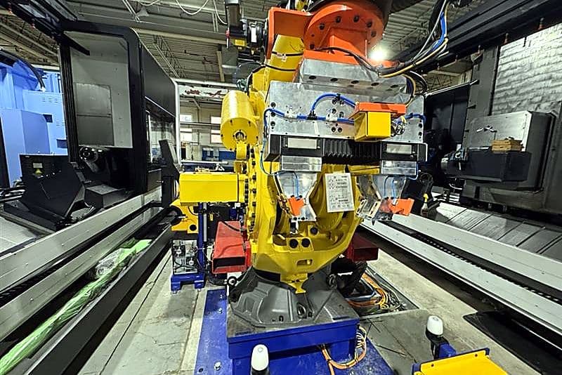
The system was built around a FANUC M-900iB/700E, a heavy payload robot, carrying a Schunk ELG-120 servo gripper. The mechanical design team modified the gripper on the Ethos floor to correct a weight imbalance at the robot's wrist axis, and ran formal load calculations through the gripper manufacturer's application engineering group to validate the result. Those calculations set a hard constraint the rest of the design had to respect: with a factor of safety of two, the part could not tilt more than ten degrees from horizontal during handling.
Challenge One: Controlling Force, Not Position
Most robotic grippers are commanded to a position. Close to this dimension, stop. On a forged part whose incoming dimensions vary, and where too much clamping force damages a surface that will spend decades inside a reactor, position control is the wrong tool.
So the cell was built on torque control instead, and that turned out to be considerably harder than it sounds. In the automation team's own account:
"The primary technical challenge was that we were not controlling position, but torque, in order to reliably grip a relatively heavy part. This introduced variability and instability in the system. The gripper motor would experience excessive load while attempting to generate enough torque to prevent the part from slipping. This led to frequent overcurrent alarms. Additionally, we began encountering In-Position timeouts, as the gripper was unable to stabilize and maintain its commanded position under dynamic load conditions."
The fix was not a setting. It was a strategy, arrived at by iteration, and the robot program archive records the search: an original digital I/O gripping routine, abandoned. A second attempt, abandoned. A torque-monitored close that survived into the final build. Then a separate, lower-force profile, because a part that has lost 90 lb (41 kg) of material in the machining centre and shifted its centre of gravity by roughly 0.6 in (15 mm) cannot be gripped the same way as the raw one. Then a collision-detection variant of that. Then a routine that verifies grip state before the robot moves at all.
The final approach picks the part at twenty five percent torque, rotates the robot, and only then commits to the reorientation, with the force profile selected according to which operation the part is coming from. Two grip profiles, chosen by the system, for what a casual observer would call the same part.
What the Gripper Must Not Do
Holding the part is only half the requirement. The other half is not damaging it.
A finished end fitting is a machined nuclear component with a thin wall, and the surfaces the gripper closes on are surfaces that will be inspected. Enough clamping force to hold 400 lb (180 kg) through a 90 degree rotation is also enough to score or indent the part, and a scored end fitting is scrap, not rework.
That rules out gripping directly on steel, so the contact faces carry pads. Choosing what those pads are made of is where nuclear stops resembling any other industry.
The obvious answer is a soft polymer, and the obvious answers are mostly disallowed. Halogens and sulphur in a contact material are a recognised contributor to stress corrosion cracking in reactor components, so a pad that leaves trace chloride on a surface destined to spend decades in a pressurised heavy water environment is a genuine problem, not a theoretical one. The customer specified limits, Ethos sent samples for independent testing, and the results came back under 100 micrograms for halogen and under 350 for sulphur. Review of those results became a formal sign-off item at factory acceptance, sitting on the same checklist as emergency stop validation and electrical inspection.
The pads that met it are PEEK, machined into custom finger designs.
An air blower was then added to the end of arm tool to clean the gripping surfaces before every pick. On a nuclear component, a chip of swarf trapped between a PEEK pad and the part is exactly the mechanism the pads exist to prevent: a hard particle, clamped at full force, pressed into a finished surface.
Challenge Two: Removing the Fence
The customer wanted the cell fully open. No perimeter guarding, for access and operational reasons.
For a heavy payload robot swinging eight foot parts between two machining centres, that is a genuinely difficult request, and there was no established precedent for the configuration. Every shortcut a fence gives you disappears. You cannot rely on a physical barrier to keep people out of the envelope, so the sensing has to do all of it, and the sensing has to work around parts large enough to cast shadows across it.
The answer was four area scanners, two at the entrance side and two at the exit, with deliberately overlapping detection fields, because standard placement could not cover the full working envelope between two machines with nothing to mount a fence to. Above that sat three zones of behaviour: clear, and the robot runs at full speed. Warning, and it drops to twenty five percent while the protected zone extends a further 0.6 m. Intrusion, and the cell takes a protective stop requiring a manual reset.
Scanner resolution was set to 70 mm, fine enough to detect an ankle, because with no guarding there is nothing to stop someone's foot entering at floor level.
Two details from this work are worth dwelling on, because they show what fenceless actually costs.
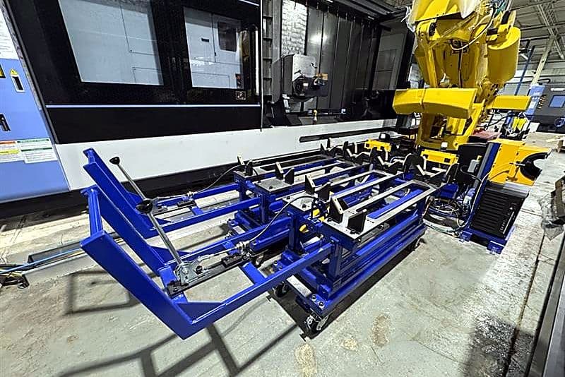
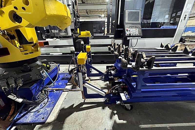
The first is that the carts became part of the safety system. All four have to be docked, with non-contact safety switches in a permissive state, before the cell will run at all. A cart in this design is simultaneously a part fixture, a transport device, and a physical barrier. That is not how carts normally work, and it exists because the geometry left dead zones between docked carts that no off-the-shelf scanner arrangement could cover. Those gaps were closed with angled physical obstructions and visual warning marking, which is not an elegant solution so much as an honest one.
The second is stopping distance. A heavy payload robot carrying 400 lb does not stop quickly, and with no fence, the distance it travels while stopping is the distance a person could be standing. So it was measured rather than assumed. Scanner response time of 336 milliseconds, robot stopping time of 322.6 milliseconds, total system stopping time of 0.6586 seconds, giving a minimum safe distance of 2.25 m. Every scanner zone was laid out against that number.
Underneath all of it, the robot's own dual check safety was configured to monitor speed and zones independently of the safety PLC, so the cell has two separate systems watching the same thing.
The pre-start health and safety review was completed by an external engineering firm in October 2025. It passed with no recommendations required.
Challenge Three: The Process Changed, Twice
In April 2025, with the cell being assembled at Brantford, direction came through to change the process.
The original design split the operation between the two machining centres. The revision was one-piece flow, each machine running the complete part, so that one machine going down would cost throughput but not stop production. The logic was sound, and the team rebuilt the sequencing around it.
Then it changed back. The workholding in the machining centres could not accommodate both part diameters in an automated one-piece flow, and that discovery forced a return to the split operation. Between the two changes, the robot program and the CNC signal sequences were restructured twice.
This is the part of a project that never appears in a brochure, and it is exactly the part that separates integrators. The cell that exists today is the third architecture attempted, and it works because the team was willing to tear up its own work twice rather than force a process the machines could not physically support.
Challenge Four: Writing an Interface That Did Not Exist
Ethos did not own the machining centres, the CNC programming, or the measurement system. What Ethos owned was making a FANUC robot, an Allen-Bradley safety PLC, two Doosan turning centres, a probing system and a laser marker behave as a single machine. There was no published protocol for that combination.
The controls lead described the starting position plainly:
"We started with rough documentation from the CNC supplier, which was based on a FANUC controller setup. The documentation was not detailed enough to follow directly, so it became our starting point and we had to iterate from there. We would get a sequence working in one operating mode and then find it would fault or drop signals in another. The revisions were a direct result of reconciling what the CNC actually needed versus what the manual said it needed."
The interface map went through five revisions over seven months. The PLC program accumulated more than fifty user revisions. The timing chart defining how signals had to be sequenced was requested five consecutive weeks running before it arrived, which meant the team was programming an interface while the specification for it was still being written.
The probing integration was harder still, by the same lead's account, because it added a third link to the chain and had even less documentation behind it. It took twenty to thirty iterations across three to four days on site to get measurement data arriving reliably and in a form the PLC could act on. The probe result determines whether a finished part passes or fails. A failed part completes its normal path to the outbound cart and stays flagged on screen so an operator reviews the measurement data before deciding what to do with it. A rejected part is never marked.
Challenge Five: When the Recovery Plan Was the Wrong Plan
The first fault handling architecture was built on in-place recovery: more than twenty programs covering every combination of machine and pick position, each trying to nurse a mis-loaded or dropped part back into the sequence.
It was abandoned in full. The final build replaces all of it with a different philosophy. If a part cannot be placed correctly, stop trying to recover it in place, route it out of the cell as a reject on a collision-safe trajectory, and get back to production. Reject positions, mis-load handling per machine, and infeed rejection replaced the entire recovery tree.
The cell now recognises forty four distinct fault conditions, each with a defined cause and a stated recovery action. Very few of them require anyone to go near the robot.
Challenge Six: Marking a Part Nobody Had Specified Yet
Nuclear components require full serialisation. Every part carries an identity, and that identity has to survive the process and be provable afterwards.
The system handles this by making the data drive the machine rather than describe it. An operator docks a cart, and RFID on the cart confirms it is where the system thinks it is. Three barcodes are scanned on each part within a ninety second window. From that scan the system resolves the variant, which selects the machining programme and the expected bore size. The record then travels with the part, and the robot will not pick unless both a physical part and a complete tracking record are present, and will not drop unless the destination is empty of both.
The complication was that the marking specification itself did not exist when development started, and kept moving for roughly ten months. Marking requirements first appeared in March 2025. Barcode samples followed in May. Formats were revised in August. A variant lookup table arrived in November. Barcode drawings for the variants landed in January 2026. At one point the marking text sat unresolved for seven consecutive weeks.
The build absorbed several genuine failures along the way. The first labels printed would not scan, because the format that came out did not match what the documentation specified. The data mapping between PLC and CNC had to be widened from 32 bytes to 48 after it became clear the part number needed ten characters and the original allocation was simply too small. And the laser itself could not be coaxed into producing a reliably readable mark until the manufacturer's support team replaced the unit with a higher powered one, after which every marking parameter had to be re-established from scratch.
Testing was made harder by not having machined and unmachined variants available at the same time, which meant some conditions could not be proved in sequence and had to be revisited later.
The Result
The cell was bought off at site and signed on 30 October 2025.
On the portion of the process Ethos was responsible for, the robot moves and the traceability system, the cell ran at better than 95 percent OEE during the on-site run. That figure deliberately excludes machining time, which belongs to the machines and the programs running in them.
Total cycle time is governed by how much metal has to come off, and varies by operation. The part Ethos controls does not. From robot pick to placement inside the first machining centre, including the machine door opening and closing, is under thirty seconds.
The pre-start health and safety review and laser safety inspection both closed in October 2025. The operations manual and the full documentation package, covering mechanical and electrical drawings, safety documentation, code and process mapping, closed in November. Production support ran in January 2026.
What the plant has is a cell where an operator loads a cart, scans barcodes and walks away, and where eight foot nuclear components are turned, measured, marked and stacked without a crane, a sling, or a second person on the other end of the load. On a line that runs around the clock, seven days a week, that is a great many lifts that now happen without anyone underneath them.
A Note on Installations
One honest observation from this project, offered because it is common to the industry rather than particular to this customer.
Ethos tracked its own installation efficiency at site and found time lost to sequencing rather than to engineering: power drops and air lines arriving later than planned, floor cable trays needing cutting on the day, multiple trades working the same footprint at once, and equipment positions adjusted slightly after layout. None of it unusual. All of it expensive.
Site readiness is a shared problem, and the integrators who plan for it, rather than assume it, are the ones who hit their dates. It is now a standing part of how Ethos plans installation windows.
What It Enabled
The clearest verdict on a piece of automation is whether the customer comes back.
In March 2026 they did, with a change: mark the parts on both sides. It was scoped, issued on a new purchase order, delivered, and signed off on 25 May 2026. Roughly eighteen months after kickoff, the same integrator and the same sign-off sheet.
Meanwhile the schedule story is worth recording accurately, because it is the part most integrators would quietly leave out. Final cell testing slipped thirteen weeks and run-off eleven, driven by machining centre delivery from overseas and site readiness. Across the same period, every milestone that belonged to Ethos landed on or ahead of target: factory acceptance on the day, shipment on the day, installation on the day.
The nuclear retrofit programs in Ontario run for years yet. The parts will keep coming.