
Every megawatt of AI compute reaches its servers through a transformer. Data centre buildout, grid modernisation and electrification have all landed on the same supply chain at the same time, and transformer lead times have stretched from months into years. The constraint is not chips. It is the unglamorous electrical equipment between the grid and the rack.
Which makes it worth knowing how a transformer core is actually made.
Inside every transformer is a core of laminated electrical steel: thin strips, bent and stacked in successive rings, one wrapped around the last. A single core takes between 83 and 140 of them. Until recently, at the manufacturer in this case study, every one of those laminations was placed by hand.
Not because nobody had thought of automating it. Because nobody had managed it.
Why It Stayed Manual
The reason is in the hands.
An operator building a core has to hold everything already placed tightly together while threading a new lamination around the outside. Let the stack relax and it unravels. Human hands do this without thinking: grip, tension, spread, place, keep the pressure on. Replicating that is a genuinely hard robotics problem, and before this project Ethos found no evidence anyone had solved it. Vendor conversations and an open-source search turned up nothing. The process had never been automated.
The tolerance for getting it wrong is also lower than it looks. Gaps between laminations and misalignment in the stack are not cosmetic defects. They cause eddy current losses and, at worst, short circuits in the finished transformer. A core that looks fine and is stacked badly is a failure waiting to be energised.
Add the variation. Five core sizes in scope. Laminations differing in length, thickness and bend angle across the range. And a target of twelve seconds per lamination, covering feed, cut, pick and place.
The machine also has to absorb a demand pattern that never settles. The five products are not built to a forecast, they are built to orders as they arrive, so the mix changes constantly and there is no steady annual volume to design around. Whatever the cell did, it had to do across all five sizes, in whatever order the work came in, with one operator per machine across three shifts.
So the manufacturer did not ask for a production line. They asked whether the thing was possible at all.
Three Stages, Five Prototypes
Ethos ran a proof of principle before quoting a system. It started in February 2023 and split the problem into the three things that had to work independently before any of them could work together:
- Getting a lamination out of the bender and presented to a robot
- Getting a robot to hold and spread it
- Getting it stacked into a core
Each stage was explored through concepts, then built as a prototype and tested. Five prototypes in four months. Two of them failed, and the failures are the reason the production system works.
Stage One: Four Ways to Catch a Lamination, Three of Them Wrong
The first question was how a floppy strip of steel leaves a bender and arrives somewhere a robot can find it.
Four families of concept were considered, and the record of why three were dropped is more useful than the one that survived.
Gripping the lamination while it was still in the bender was rejected because large laminations shake as they are fed, and waiting for them to settle burns cycle time nobody had. On small laminations there is less than half an inch of rigid material to grip, which leaves the part loose and unpredictable in transit. On large ones, that same half-inch grip plus fast robot motion risks deforming the part at the grippers.
A bucket to catch the ejected part was rejected because the spread of lamination sizes would need several bucket sizes, because a part in free fall can land in any orientation, and because catching it still leaves the problem of presenting it to a robot.
What survived came out of the bucket concept by removing its base: a magnet to hold the lamination through bending and cutting, then a chute to carry it to a fixed end stop.
The fourth concept, a pivoting table with integrated magnets, came from the customer's own engineer rather than from Ethos. It was prototyped alongside the magnet arm rather than dismissed.
Before any of this was drawn in CAD, someone ran a test on the shop floor to find out what angle a stainless chute needs to move a lamination reliably. Too steep and it runs away, too shallow and it stops partway. The answer was 23 to 24 degrees. That number then constrained everything designed after it.
Testing in the Plant, by Hand
On 23 March 2023, two Ethos engineers and two from the customer put both prototypes on a live bender and ran real laminations through them.
The prototypes had no pneumatics and no actuators. They were operated by hand, with people performing the motions the machine would eventually make. That is a deliberate choice: it tests the geometry and the physics without spending money on controls for a concept that might not survive the morning.
Both worked. And the test produced a set of numbers that no amount of design review would have found:
A lamination can be compressed against the machine during the pick, but by no more than about 30 percent of its width, or the bend angle changes. A stainless chute has the right friction and wear life, but an edge can still catch and jam, so air nozzles along its length are needed as a redundant way to move the part. The chute's end stop and walls have to cover roughly 30 percent of the lamination's seated height to stop it falling out, while still leaving an inch to an inch and a half of material exposed for a gripper to reach. And the magnet faces, left bare on the prototypes, need shielding behind stainless steel in production.
The pivot table worked too, but it is limited by the size of the opening in the bender it has to occupy. The magnet arm scales better. That is why the magnet arm went forward, and the reasoning is recorded rather than assumed.
Stage Two: The Prototype That Failed, and the Roll of Tape
The end of arm tool had to do what the operator's hands do: pick a lamination, spread it, and lower it around the growing core.
Spreading was chosen early, for two reasons. It is what the humans already do, and it keeps the part square to the machine's axes, which makes the robot's job simpler.
The design logic from there is unusually legible. A rotational spread, scissor-like, gave way to a linear one, because linear is lighter and simpler, and the weight of an end of arm tool drives the size of the robot, which drives the cost of the cell. Fixing one gripper in place and moving only the other gives the robot a fixed datum to work from, which means less sensing, which means less cost and less cycle time. It also means one servo instead of two.
Then they built it, and it did not work.
The gripper fingers were designed to roll, letting the lamination travel between them as it spread. In practice the roll was asymmetric and uncontrolled. Laminations came out of alignment, and sometimes came out of the grippers entirely. The finger material could not generate enough friction to hold the larger parts horizontally at all.
What happened next is the most instructive moment in the project. Rather than redesign and rebuild, someone removed one roller finger from each gripper and taped the lamination to the remaining finger, physically simulating a gripper that swivels instead of rolls. The spread came out smooth and symmetric immediately.
A failed prototype and a roll of masking tape established the production design rule: one fixed gripper and one driven along a rail, each able to swivel to follow the shape of the part as it stretches. Square gripper faces, not rollers, at least half an inch by an inch, in polyurethane rather than nylon. Parallel fingers with up to three inches of stroke to absorb the variation in where the lamination actually sits. And not shoulder bolts in bronze bushings, which work vertically but jam under the side loading this tool sees.
Stage Three: Failing on Purpose
Ethos said at the outset that assembly would be the hardest of the three stages, and it was.
The first concept clamped the laminations together with pneumatic cylinders on the outside faces. Watching the manual process changed it. A core cannot be squeezed from four sides at once; it has to be clamped progressively, face by face and corner by corner, and the customer proposed the sequence.
The prototype built to test that sequence was deliberately simplified for budget and speed, cut from eight spring clamps down to four corner clamps. It could not assemble a complete core.
It also produced the single most valuable finding in the proof of principle. A transformer core is not square. It is slightly convex. A square inner fixture only touches part of each face and leaves gaps at the corners, so the fixture the laminations wrap around has to be convex too. That is not something a drawing tells you. It is something a failed fixture tells you.
The same prototype established that chamfers used to guide laminations down onto the stack need to be steeper than 45 degrees and cut in hardened steel, because the razor edge of electrical steel cuts into aluminium and seizes. That clamping the faces either side of a corner is not the same as clamping the corner, and leaves gaps at the vertex. That the face carrying the lamination seam has to be clamped in sequence for the overlap to come out right. That the first lamination has to be laid 180 degrees to every one above it, or the finished core is not rigid enough to lift off the fixture. And that the internal fixture has to collapse or withdraw, or an operator cannot get the core off it without damaging the inside layer.
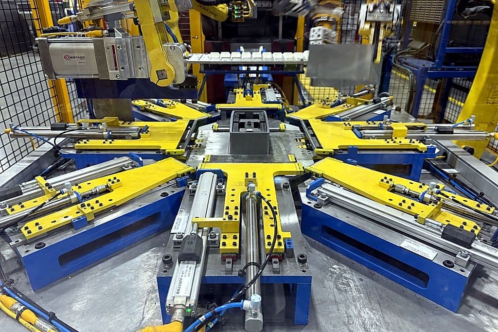
The fifth prototype answered all of it: laminations loaded from overhead by the robot, a top layer of rollers squaring and massaging each new face into place, a bottom layer holding constant light pressure so the last one does not move, and a tamp from above.
Fifty iterations of clamping and fixture design went into getting that right.
What the Proof of Principle Bought
At the end of it, the customer had something more useful than a quotation. They had evidence, with the failures included and the reasoning written down.
That is the argument for proofs of principle generally. The alternative is a specification that promises everything, a purchase order, and the discovery of what is actually hard six months later with the cell half built.
But this project also demonstrates the limit of that argument, and it would be dishonest to leave it out.
Where the Proof of Principle Was Wrong
The magnet and chute concept that survived the proof of principle did not survive production.
In the real cell, pickup was inconsistent. Laminations jammed in the bender. The magnets sometimes grabbed the wrong face. The cause was the same variation that had shaped the whole project, now defeating the sensors: lengths, angles and thicknesses all moving at once.
The fix was to stop waiting for the part. The magnet assembly was moved onto a robot, which now travels to the bender and collects the lamination as it is cut. That bought control and cost cycle time, in a window only four seconds wide, and it put two robots into the same physical space with no room for a shuttle to separate them.
Ethos bought that robot at its own cost, and the reason is worth setting out, because on paper it was unnecessary.
The original design used a servo slide and a cylinder to pull the lamination out of the bender. It was not a failure. It worked about 90 percent of the time. The contract required 85 percent OEE, so a mechanism running at 90 would have met the specification and the project could have been closed out against it.
Two things made that unacceptable anyway. The first is the cycle time the cell was held to: at twelve seconds a lamination, with 83 to 140 of them in a core, a failure every tenth pick is not a rounding error, it is a stoppage every couple of minutes. The second matters more. When this line stops, the people who get it running again are the customer's maintenance team, not Ethos. A mechanism that needs judgment to recover is a mechanism that costs the plant real downtime long after the integrator has gone home.
So the target stopped being the contractual 85 percent and became better than 99. Getting there meant the flexibility of a robot rather than a fixed-stroke slide, and since the robot was not in the quoted scope, Ethos paid for it.
That is a decision that costs money in the year it is made and earns it back over the life of the relationship. It is also the difference between passing an acceptance test and handing over something the customer can actually run.
Then there was the sensing, which is the hardest problem in the file. Three laser distance sensors measure where the lamination is. Too close and the part gets crushed. Too far and the magnets will not engage. With multiple bends in every part, and length and thickness varying across the range, there was no common reference point to measure from. No single feature existed on every lamination that the sensors could trust.
They hit the cycle time anyway, including a second pickup in the sequence.
The Failures That Only Appear on a Real Floor
Two more problems surfaced only after the cell was integrated on site.
Inconsistent dents appeared on the inner face of the laminations, traced back to the rollers. And the shoulder bolts holding those rollers began working loose after more than two hundred cycles, which is far enough into production to look like a solved system and close enough to the start to be a serious problem.
Both were fixed by material and mechanism rather than by adjustment. The fixture block was remade in A2 heat-treated tool steel, hard enough to stop the denting. The rollers were redesigned around integral studs rather than shoulder bolts, which removed the loosening entirely.
The compression tooling also changed: two layers of rollers instead of one, upper and lower working together to hold the stack and push each new layer in, with a larger tamp from above. Sequencing those rollers and balancing the pressure between the layers took until early 2025.
The Clip
One detail sums up how far this went past the original brief.
When an operator finishes a core by hand, they tape or band it so it does not spring open the moment the pressure comes off. An automated cell that cannot do that has not finished the job.
So Ethos designed a clip, 3D printed and iterated until it would hold cores of varying size and thickness against high compression force, and taught the robot to pick it up and fit it. That took precise positioning and controlled tension, and careful calibration so the core stayed stable through the transfer.
The automation does not stop at the last lamination. It stops where the operator's hands used to.
The Result
The cell runs at a twelve second average per lamination: 10.8 seconds on the smaller cores, 11.8 to 11.9 on the larger ones. A complete transformer core, 83 to 140 laminations depending on size, comes off the fixture in twenty to thirty minutes.
There is no headline figure for cores per year, and it would be misleading to invent one. The plant builds to orders as they come in rather than to a forecast, across five products, so the volume and the mix move constantly. What changed is not a number on a capacity chart. It is that the operation no longer runs at the speed of a pair of hands, and the output no longer depends on which operator is on which of the three shifts.
The process that had never been automated is automated, across five core sizes, in whatever order the work arrives, with a clip fitted by a robot.
Why This Matters Now
The grid is the constraint on the AI buildout, and transformers are the constraint on the grid. Capacity in that supply chain is not limited by demand or by capital. It is limited in part by how many processes still depend on a pair of experienced hands and cannot be run any faster than those hands can move.
This was one of them. It is not any more.
The method is worth as much as the cell. Two failed prototypes, a hand-operated test on a live machine, a roll of tape, and fifty iterations of a fixture produced a system that works, and produced it before anyone committed to building the wrong thing. That is not a story about robots. It is a story about finding out early.